Cart-Pole Control
REFERENCE: This tutorial borrows contents from Daniel’s and Professor Green’s websites, special thanks to them! If you want to refresh your memory about state feedback control, check this video tutorial by Brian Douglas. If you are interested in learning more about non-linear dynamics and control (the theory behind Atlas), check this course taught by Professor Russ Tedrake.
Introduction
The cart and pole task is a classical benchmark problem in physics, control theory, and reinforcement learning. It is also known as the inverted pendulum, or pole/stick/broom balancing task. This system is a simple and valuable laboratory representation of an unstable mechanical system. It is also often used to model the control problems encountered in the flight of rockets and missiles in the initial stages of launch, when the airspeed is too small for aerodynamic stability.
Consider the physical model shown below. A cart is positioned on a track running horizontally, and an inverted pendulum is attached to the cart with a hinge that allows rotation around pivot point in the xy plane only, i.e. the pendulum is free to fall horizontally left-right, but not ‘out’ of the diagram. The pendulum’s initial position is near vertical, and a external variable horizontal force is applied to the cart to maintain the pendulum in a balanced and upright position.
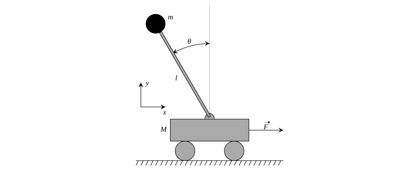
The model is considered to represent an unstable system because an external control force is required to keep the pendulum balanced; as opposed to a downward hanging pendulum in which the force of gravity alone results in stable oscillation about the downward vertical. We will assume an ideal pendulum, in which all of the pendulum’s mass is located at a single point at the end of a massless rigid rod.
Equations of motion
We denote the horizontal displacement of the cart by \(x\), and the counter-clockwise rotation angle of the pole by \(\theta\). The state of the system is denoted by a vector \(\mathbf{x} = \left[\begin{array}{c} x & \dot{x} & \theta & \dot{\theta} \end{array}\right]^T\) and the input to the system is the horizontal force \(F\) applied to the cart, which is denoted by \(u = F\) to follow the convention. If the task is to stabilize the system at the unstable fixed point, the reference vector is in the form of \(\mathbf{r} = \left[\begin{array}{c} x_r & 0 & 0 & 0 \end{array}\right]^T\) where \(x_r\) can be an arbitray. To keep it simple, we assign \(x_r = 0\).
The dynamics of the cart pole system is determined by evaluating the system using Lagrangian Mechanics. The Lagrangian of the cart pole system uses the general energy equation \(L = T – V\) where \(L\) is the Lagrangian term generalizing the total energy in the system, \(T\) is the kinetic energy of the system, and \(V\) is the potential energy of the system. The potential energy of the system is \(V =mgl\cos (\theta)\). The kinetic energy of the cart is \(T_c = \frac{M\dot{x}^2}{2}\), and the kinetic energy of the pole is:
\[T_p = \frac{m\left(\dot{\theta}^{2} l^{2}+2 * \cos (\theta) \dot{\theta} \dot{x} l+\dot{x}^{2}\right)}{2}\]The kinetic energy of the system is:
\[T = \frac{M \dot{x}^{2}+m\left(\dot{\theta}^{2} l^{2}+2 * \cos (\theta) \dot{\theta} \dot{x} l+\dot{x}^{2}\right)}{2}\]The equations of motion are then derived by the Euler-Lagrange Equations and rewrote in the following form:
\[\left[\begin{array}{c} \dot{x} \\ \ddot{x} \\ \dot{\theta} \\ \ddot{\theta} \end{array}\right]=\left[\begin{array}{c} \dot{x} \\ \frac{-m l \sin (\theta) \dot{\theta}^{2}+F+m g \cos (\theta) \sin (\theta)}{M+m\sin^2 (\theta)} \\ \dot{\theta} \\ \frac{-m l \cos (\theta) \sin (\theta) \dot{\theta}^{2}+F \cos (\theta)+m g \sin (\theta)+M g \sin (\theta)}{l *(M+m \sin^2 (\theta)).} \end{array}\right]\]The above equations govern the system dynamics of the POP cart-pole simulation. Note how the motion of cart and pole are coupled.
These non-linear eqiatopms need to be linearized in order to implement a linear controller. Note that at the reference state \(r\), \(\theta \approx 0, \dot{\theta} \approx 0\). Thus, \(\sin (\theta) \approx \theta\), \(\sin^2 (\theta) \approx 0\) and \(\cos (\theta) \approx 1\), and the above equation is linearized as
\[\left[\begin{array}{c} \dot{x} \\ \ddot{x} \\ \dot{\theta} \\ \ddot{\theta} \end{array}\right]=\left[\begin{array}{c} \dot{x} \\ \frac{F+mg\theta}{M} \\ \dot{\theta} \\ \frac{F+(M+m)g\theta}{Ml} \end{array}\right]\]Rewrite the above equation in the state-space equation form \(\dot{\mathbf{x}} = \mathbf{A}\mathbf{x}+ \mathbf{B}\mathbf{u}\), where
\[\mathbf{A} = \left[\begin{array}{c} 0 & 1 & 0 & 0 \\ 0 & 0 & \frac{mg}{M} & 0 \\ 0 & 0 & 0 & 1\\ 0 & 0 & \frac{mg+Mg}{Ml} & 0 \end{array}\right], \mathbf{B} = \left[\begin{array}{c} 0 & \frac{1}{M} & 0 & \frac{1}{Ml} \end{array}\right]^T\]Then, pole placement control can be designed.